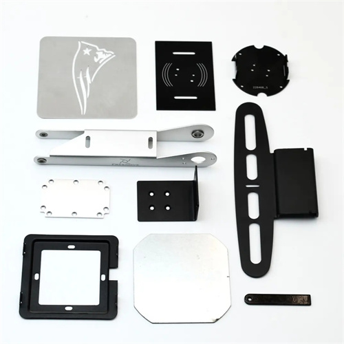
Blanking die handle
The die handle of a shearing die is a key component that connects the upper die to the press’s slide. Its primary function is to accurately mount the die on the press and transmit the press’s power to the die’s working part. The structural design of the handle directly affects the die’s installation accuracy, stress distribution, and stability during the stamping process. Therefore, when designing a shearing die, the type and size of the handle must be carefully selected based on the press type, the die’s structural characteristics, and the stamping process requirements. The handle not only ensures the die’s correct positioning on the press but also withstands axial forces and eccentric loads during the stamping process, preventing the die from shifting or vibrating during operation.
There are many types of die handles for punching dies, including flanged handles, press-in handles, screw-in handles, floating handles, and universal handles. Each type has its own application scenarios. Flanged handles are connected to the upper die base via bolts and are suitable for large punching dies. Their larger flange diameter provides better support and positioning. Press-in handles are pressed into the handle hole of the upper die base with an interference fit, providing a secure connection and suitable for small and medium-sized dies. Screw-in handles are connected to the upper die base via threads, making them easy to assemble and disassemble and suitable for dies that need to be frequently replaced. Floating handles can compensate for installation errors between the die and the press through spherical contact, reducing the impact of eccentric loads on the die, and are suitable for precision punching dies. Universal handles can adapt to presses of different specifications through an adjustment device, offering high flexibility and suitable for small-batch production of multiple varieties.
The dimensional parameters of the die handle must match the mounting hole of the press slider, including the die handle diameter, length, and fit accuracy. The die handle diameter should be consistent with the press slider hole diameter, usually using a transition fit of H7/m6 to ensure that the die handle can be installed smoothly without creating excessive gaps that cause the mold to shake. The die handle length needs to be determined based on the thickness of the upper die base and the depth of the press slider hole. Generally, after the die handle is installed in the slider hole, there should be a gap of 1-3mm between its end face and the bottom surface of the slider hole to avoid deformation of the upper die base due to excessive length. For large molds, the die handle diameter should be appropriately increased to improve its load-bearing capacity. For example, when the press tonnage is 1000kN, the die handle diameter is usually not less than 60mm.
The material selection and heat treatment of the die handle are crucial to its strength and wear resistance. The die handle is typically made of high-quality carbon structural steel, such as 45 steel or 40Cr. 45 steel requires quenching and tempering to a hardness of 28-32 HRC to ensure sufficient strength and toughness. For molds subject to heavy impact loads, the die handle can be made of alloy structural steel, such as 35CrMo. After quenching and tempering, the hardness reaches 32-36 HRC to improve fatigue resistance. The working surface of the die handle must be ground to a surface roughness of less than Ra1.6μm to reduce friction with the press slide bore and facilitate installation and removal. Furthermore, the connection between the die handle and the upper die base must be sufficiently strong to prevent loosening or breakage during the stamping process.
The installation and debugging of the die handle are important links to ensure the normal operation of the punching die. Before installation, the dimensional accuracy and surface quality of the die handle need to be checked to ensure that they meet the design requirements; during installation, the verticality of the die needs to be corrected with a dial indicator to ensure that the axis of the die handle coincides with the moving axis of the press slide, with an error not exceeding 0.05mm/m, to avoid eccentric loads. For floating die handles, their spherical clearance needs to be adjusted to ensure that the die can float freely during operation and compensate for installation errors. During the debugging process, the stress state of the die handle during stamping needs to be observed. If the die handle is found to be bent, deformed or loose, it should be stopped immediately, the cause should be checked and repaired. Through reasonable design and correct installation of the die handle, the stable operation of the punching die on the press can be ensured, and the quality of stamping parts and the service life of the die can be improved.