Design of the clamp bending die
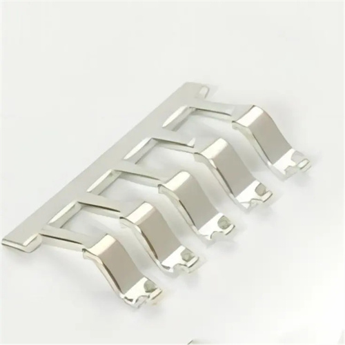
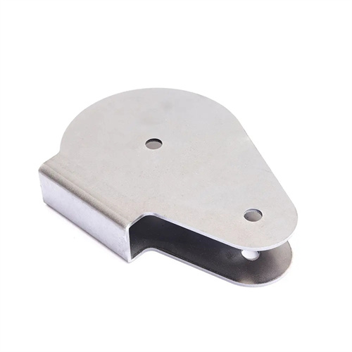
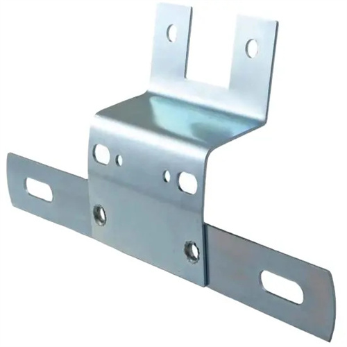
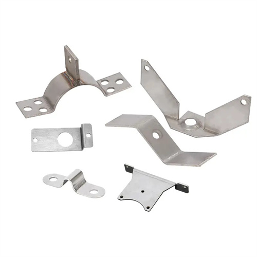
The design of a clamp bending die is a technology for bending ring-shaped or U-shaped clamps. Widely used in applications such as pipe fastening and automotive wiring harness tightening, it achieves high-precision bending of the clamp, ensuring uniform clamping force and reliable assembly. Clamps are typically made of spring steel (such as 65Mn) or stainless steel (such as 304), with thicknesses typically ranging from 0.5 to 2mm. Bend angles typically range from 180° (ring-shaped) to 90° to 120° (U-shaped). Die design focuses on addressing springback control and dimensional consistency. At the beginning of the design, the bending force needs to be calculated based on the unfolded length of the clamp, the bending radius (usually 1-3 times the material thickness) and the yield strength of the material. The formula is F=K×B×t²×σb/(r+t) (K is the coefficient, B is the width, t is the thickness, σb is the tensile strength, and r is the bending radius). For example, a 65Mn clamp with a thickness of 1mm and a width of 20mm (σb=980MPa) has a bending force of about 8-12kN, and a press with a capacity of more than 20kN needs to be selected.
The die structure consists of a bending punch, a die, a positioning device, a press mechanism, and a springback compensation mechanism. The bending punch is made of Cr12MoV alloy tool steel, hardened to HRC 58-62, and the working surface is polished to Ra 0.8μm or less. The punch corner radius is 0.1-0.2mm larger than the part requirement to allow for springback. The die is made of Cr12 steel, hardened to HRC 55-58, and the die slot width is 1.1-1.2 times the material thickness. For a 1mm thick clamp, the slot width is set to 1.1-1.2mm to ensure smooth material entry during bending. The positioning device combines a stop pin and a lateral guide plate. The stop pin controls the longitudinal dimension (accuracy ±0.1mm), while the lateral guide plate limits lateral deviation (clearance 0.05-0.1mm), ensuring accurate positioning of the blank in the die.
Springback control is the core technology of the clamp bending die, utilizing a combined “bending + shaping” process. For materials with significant springback (springback angles of 3°-5°), such as 65Mn, the punch design angle is 3°-5° smaller than the part’s required angle (overbending by 3°-5°), leveraging the die’s rigidity to force plastic deformation of the material. At bottom dead center, a spring-loaded ejector pin at the bottom of the die applies 10-15 MPa of upward pressure to shape the bend, further eliminating internal stress and keeping the final springback angle within 0.5°. For stainless steel clamps, a 0.5°-1° slope can be set in the die notch to utilize friction between the material and the die to suppress springback and reduce part removal.
The hold-down mechanism ensures a stable bending process. Polyurethane rubber (hardness 70-80 Shore A) or springs provide the hold-down force, which is 20%-30% of the bending force. For bending forces of 8-12 kN, the hold-down force is set at 2-3 kN to prevent the blank from slipping during bending. A clearance of 0.05-0.1 mm between the hold-down plate and the punch ensures flexible movement while effectively restraining the material. For the U-shaped clamp, the hold-down plate must be designed to align with the punch contour, applying pressure to both bending arms simultaneously to prevent distortion.
Commissioning and batch production control require attention to detail. During mold trials, the bending angle is measured with an angle ruler. Twenty pieces are sampled per batch. If the angle deviation exceeds 1°, the punch angle needs to be adjusted (by 0.5° at a time). A tensile testing machine is used to test the clamp’s clamping force (typically 50-100N is required). If the clamping force is insufficient, the bending angle needs to be increased or the material hardness needs to be adjusted (HRC 40-45 for 65Mn). During routine maintenance, the corner radius of the punch and die should be reground every 5,000 cycles (when wear exceeds 0.1mm) to maintain a sharp edge. The positioning stop pins should be inspected weekly and tightened promptly if loose to ensure positioning accuracy. For batch production, the mold should be equipped with an automatic feeding mechanism with a feeding accuracy of ±0.1mm. A photoelectric sensor should be used to detect the presence of blanks, enabling fully automated production and improving efficiency.