Design of Bending Die for Closed and Semi-closed Parts
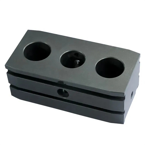
The design of bending dies for closed and semi-closed parts is a special mold technology developed for bending parts with closed or semi-closed structures (such as bearing seats, clamps, and annular brackets). The bending angle of such parts is usually more than 180° (closed parts) or between 90° and 180° (semi-closed parts). During the forming process, the material is prone to rebound, wrinkles, and dimensional deviations. Therefore, the mold design needs to focus on solving the problems of forming interference and rebound control. In the early stage of design, the bending method needs to be selected according to the degree of closure of the part, material thickness (1-5mm) and mechanical properties. Closed parts usually adopt the two-step method of “pre-bending + final bending”. Semi-closed parts can be bent and formed in one step. For example, an annular semi-closed part with a diameter of 80mm (opening 10mm) can be directly formed by a single-process bending die.
The mold structure is divided into integral and split types according to the degree of closure. The closed part bending mold adopts a split die, which consists of two left and right modules, connected to the lower die seat by a hinge. When bending, the module moves inward with the punch, and is reset by spring drive after the closed forming is completed. The module material is Cr12MoV, quenching hardness HRC58-62, and the working surface is inlaid with wear-resistant alloy sheets (such as ZGMn13) to improve the impact resistance. The semi-closed part bending mold adopts an integral die, and the radius of the inner corner of the die is 1-2 times the material thickness. For example, for a material with a thickness of 2mm, the fillet is set to 2-4mm to avoid excessive stretching of the material during bending. The punch adopts a stepped structure, the head first contacts the material for pre-bending, and the root completes the final forming. The punch material is W6Mo5Cr4V2 high-speed steel, quenching hardness HRC62-65, to ensure wear resistance under high strength.
Springback control is central to design, requiring compensation to be tailored to the material’s properties. For materials with high plasticity, such as mild steel, the bending angle of the closed part requires a 1°-2° springback compensation, and the die angle should be 1.5° smaller than the part’s required angle. For materials with a lower elastic modulus, such as aluminum alloy, this compensation should be increased to 2°-3°. Springback in semi-enclosed parts can be achieved through a “bending + shaping” process. This involves bending the punch at bottom dead center, increasing the bending angle by 3°-5° above the target value. This leverages the rigidity of the die to force plastic deformation of the material and reduce springback. Furthermore, a spring-loaded ejector pin can be positioned at the bottom of the die to apply a pressure of 10-20 MPa to the bottom of the part during the bending process, eliminating internal stress and further suppressing springback.
The positioning and guiding system needs to adapt to complex forming actions. The closed part bending die adopts “internal support + external stop” positioning. The internal support mandrel cooperates with the inner cavity of the part (clearance 0.05 – 0.1mm), and the external stopper limits the radial displacement of the part to ensure that the bending center coincides with the center of the mold. Semi-closed parts use a combination of positioning pins and guide plates. The positioning pins are inserted into the prefabricated holes of the parts, and the guide plates control the feed direction with a positioning accuracy of ±0.05mm. The guiding device uses ball guide pins and guide sleeves. The guide pins have a diameter of 25 – 35mm and a matching clearance of 0.005 – 0.01mm to ensure that the punch and the die are accurately aligned during the bending process to avoid damage to the mold caused by unbalanced loading.
Debugging and maintenance require attention to dynamic characteristics. During mold testing, high-speed video is used to record the bending process and analyze the material flow trajectory. If local wrinkles appear, the closing speed of the die module needs to be adjusted (synchronization error <0.1s); if the opening size of the closed part is out of tolerance, it is adjusted by adding or removing the gaskets between the die modules (adjustment amount ±0.05mm). In daily maintenance, the hinge mechanism of the split die needs to be filled with grease every 500 times of operation, and the wear of the sleeve needs to be checked (replace when the gap is >0.1mm); the cutting edge of the integral die is reground every 2,000 pieces to maintain the rounded corner accuracy. For high stress areas (such as the inner corners of the die), cracks are detected every 1,000 pieces, and magnetic particle flaw detection is used to ensure that there is no micro crack expansion.