Design of multi-station bending and forming progressive die
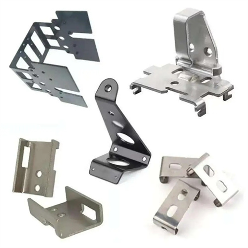
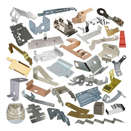
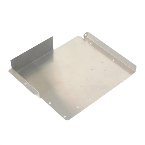
Multi-station bending and forming progressive die design is an integrated die technology developed for parts with complex bending shapes and forming features (such as automotive connectors and electrical brackets). It can continuously complete multiple processes such as punching, bending, flanging, and embossing in one die. It is suitable for mass production of steel plates, copper plates and other materials with a thickness of 0.2-3mm. Compared with traditional step-by-step processing, the consistency of part dimensions is improved by more than 40%, and the production efficiency is increased by 3-5 times. In the early stage of design, CAE simulation (such as using AutoForm software) is required to analyze the material deformation path and determine the optimal process sequence, following the principle of “punching first, then forming, simple bending first, then complex forming”. For example, a Z-shaped part with a boss needs to be bent 90° on both sides first, and then the middle boss is formed to avoid process interference.
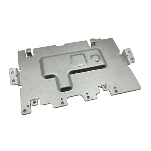
The mold structure adopts a modular combination design, which consists of a basic mold frame, multiple sets of bending male and female molds, a forming module, a feeding guide mechanism and a unloading device. The bending punch is made of W6Mo5Cr4V2 high-speed steel with a hardness of HRC62-65 after quenching. The working surface is ground to Ra0.2μm and the bending radius is polished to Ra0.1μm to reduce material scratches. The die is made of Cr12MoV steel, which is nitrided (nitriding layer thickness 0.1-0.15mm), with a surface hardness of HV800-1000 and significantly improved wear resistance. The forming module is customized according to the part features. For example, the embossing module adopts a floating structure and provides a forming force of 5-15kN through a nitrogen spring to ensure that the boss height tolerance is controlled within ±0.03mm. A guiding and straightening device is set between each workstation. The gap between the guide plate made of wear-resistant cast iron (HT350) and the strip material is maintained at 0.05-0.1mm to prevent the material from shifting during process conversion.
The bending sequence and forming parameter design need to accurately match the material properties. For brittle materials such as high carbon steel (such as 65Mn), the bending angle needs to reserve 1°-2° of springback compensation, and the die angle is 1.5° smaller than the part requirement; for plastic materials such as aluminum alloy, the compensation can be reduced to 0.5°-1°. The fillet radius of multiple bends is designed according to the principle of “first large and then small”. The first bend radius is 1.5-2 times the final radius of the part, and then gradually reduced to the target value. For example, for a part with a final fillet of R2mm, the first bend is R3mm and the second bend is R2.2mm to avoid excessive stretching of the material and cracking. The forming force calculation needs to be combined with the characteristics of each process. The bending force is calculated according to the formula F=KBt²σb/(r+t) (K is the coefficient, B is the width, t is the thickness, σb is the tensile strength, and r is the fillet), and a 15% safety factor is added to select the press tonnage.
The automatic feeding and positioning system adopts “coarse positioning + fine guiding” dual control. The feeding mechanism is a servo-driven clamp feeder with a feeding step accuracy of ±0.01mm, and the side edge trimming is used to control the positioning in the material width direction; a set of guide pins is set for every 2-3 stations, and the positioning is achieved with the previous punching to achieve ±0.005mm precision. For thin materials that are easy to deform (thickness <0.5mm), multiple sets of support wheels are set on the feeding path, with a wheel diameter of 50-80mm and a spacing of 100-150mm, to control the deflection of the strip within 0.1mm/m. A laser profile sensor is installed at the entrance of the mold to detect the edge position of the strip in real time. When the deviation exceeds 0.03mm, the feeding mechanism is automatically adjusted to ensure the longitudinal positioning accuracy.
Digital standards have been established for mold commissioning and quality control. During mold trials, high-definition cameras capture the forming process at each workstation and compare it with CAE simulation results to optimize the cutting depth of the bending punch (typically adjusted within ±0.1mm). An online measurement system performs 100% inspection of key part dimensions (such as bend angle and hole coordinates) at the final workstation. Data is uploaded to the MES system in real time, and the machine automatically shuts down if the pass rate falls below 99.5%. During routine maintenance, the bending punch undergoes precision calibration every 10,000 units. An angle gauge is used to check for angular deviation in the working section, and any deviation exceeding 0.05° is reground. Guide pins are inspected weekly and replaced if wear exceeds 0.01mm to ensure reliable positioning.