Design of guide plate guide die
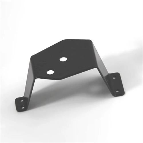
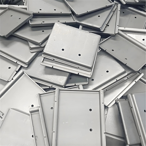
The guide plate guided die design is a type of die that uses a guide plate as a guiding mechanism in the stamping die. It has the characteristics of simple structure, reliable guiding, and low manufacturing cost. It is widely used in medium and low speed stamping, blanking and bending of small and medium-sized parts, such as the production of gaskets, small brackets and other parts. The core advantage of the guide plate guide is that the guide is achieved through the precise matching of the guide plate and the punch, avoiding the complex structure of the traditional guide column and guide sleeve guide, which is especially suitable for occasions with limited space. In the early stage of design, the matching accuracy of the guide plate and the punch needs to be determined according to the type of stamping process (such as punching, blanking, bending), part size and material thickness. Usually the matching clearance is controlled at 0.01-0.03mm to ensure that the punch does not deviate during movement and to ensure the dimensional accuracy of the stamped parts.
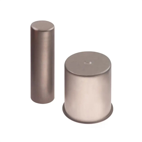
The mold structure mainly consists of an upper die base, a lower die base, a punch, a die, a guide plate, a discharge device and a positioning device. As a key guide part, the guide plate is usually fixedly connected to the lower die base. Its material is 45 steel or Cr12. After quenching, the hardness reaches HRC40-45 (45 steel) or HRC55-60 (Cr12). The working surface is ground to less than Ra0.8μm to ensure good sliding fit with the punch. The punch material is Cr12MoV, and the hardness after quenching is HRC58-62. The matching length with the guide plate must not be less than 1.5 times the diameter of the punch (round punch) or 1.5 times the width (special-shaped punch) to ensure guiding stability. The die is installed on the lower die base, and the matching clearance with the punch is determined according to the material thickness. The blanking clearance is generally 5%-10% of the material thickness, and the bending clearance is 1.05-1.1 times the material thickness to ensure the stamping quality.
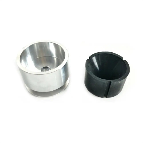
The structural design of the guide plate must satisfy the dual functions of guiding and unloading. A guide hole consistent with the shape of the punch is opened on the guide plate. The position accuracy of the hole must be consistent with the corresponding hole position of the die, and the coaxiality error shall not exceed 0.02mm. For multi-punch dies, each guide hole on the guide plate needs to be processed and formed at one time (such as by coordinate grinding) to ensure the position accuracy between the holes. The thickness of the guide plate is selected to be 15-30mm according to the size of the mold. The connection with the lower die seat is pin-positioned and bolt-fastened to ensure that no displacement occurs during the stamping process. In addition, the guide plate can also serve as a unloading plate. By setting elastic elements such as springs or rubber between the guide plate and the lower die seat, the unloading function after stamping is realized. The size of the unloading force needs to be adjusted according to the number of punches and the size of the stamped parts to ensure that the parts can be smoothly separated from the punches.
The design of the positioning device and the unloading device must be compatible with the guide plate guide. The positioning device usually adopts a stop pin, a guide plate or a positioning plate, which is determined according to the feeding direction and shape of the part. For example, for the blanking die fed by strip material, a combination of a guide plate and a stop pin is used for positioning. The spacing between the guide plates is 0.5-1mm larger than the width of the strip material. The position of the stop pin is determined according to the size of the blanking part to ensure accurate positioning of the blank. In addition to the elastic unloading function of the guide plate, the unloading device can also be equipped with a rigid unloading plate for thick materials or large-sized parts. It is installed on the upper die and connected to the upper die seat by bolts. After the stamping is completed, the part is forced out of the die. The clearance between the unloading plate and the punch must be larger than the matching clearance between the guide plate and the punch, generally 0.03-0.05mm, to avoid interference with the guiding function.
The following points should be noted when installing and using the mold. During installation, it is necessary to ensure that the guide plate and the punch cooperate smoothly. When the upper mold is pushed manually, the punch should be able to slide flexibly in the guide plate hole without jamming. The selection of the press machine needs to match the closing height and punching force of the mold. The punching force calculation needs to include the punching process force and the unloading force, and the safety factor is 1.2-1.3. When testing the mold, first run it without load, check the coordination of the movement of each component, and then test punch. Adjust the gap between the punch and the die by measuring the size and cross-sectional quality of the stamped parts. In daily maintenance, the iron filings and oil stains on the matching surface of the guide plate and the punch need to be cleaned every 500 times, and lubricating oil (such as engine oil or grease) should be applied to prevent aggravated wear. When the wear of the guide hole of the guide plate exceeds 0.05mm, it is necessary to expand the hole or replace the guide plate. When the wear of the punch exceeds 0.03mm, it needs to be replaced to ensure that the mold always maintains good guiding accuracy and stamping quality.