Design of bottom shell drawing die
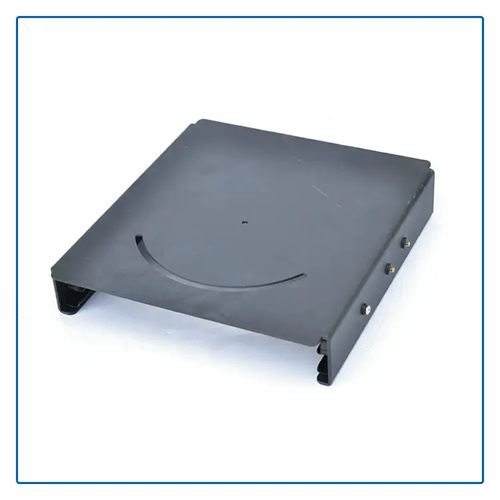
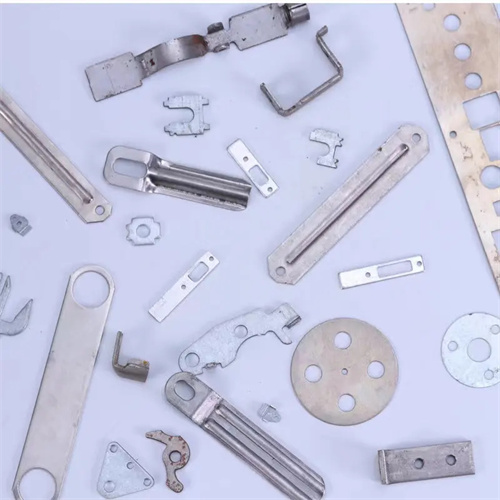
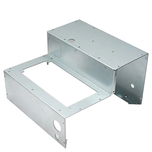
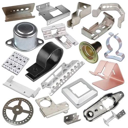
The bottom shell drawing die design is a drawing forming die for various containers and shell parts (such as motor bottom shell, instrument shell, battery shell, etc.). These parts usually have the characteristics of deep cylindrical, closed bottom, vertical or slightly tapered sidewalls, and have high requirements for bottom fillet, sidewall thickness uniformity and surface quality. In the early stage of design, it is necessary to comprehensively analyze the structural parameters of the bottom shell, including the mouth diameter, bottom diameter, height, wall thickness and material properties (such as stainless steel, aluminum alloy, low carbon steel, etc.), and determine the number of drawing times and die structure by calculating the drawing coefficient, forming height and required drawing force. For example, for a bottom shell with a mouth diameter of 100mm, a bottom diameter of 80mm, a height of 120mm, and a material of 08 steel (thickness 1mm), it is necessary to calculate the maximum possible height of the first drawing. If it exceeds the part height, multiple drawing is required, and the height of each drawing increases to ensure uniform deformation of the material.
The die structure is divided into single-process drawing die and multi-process continuous drawing die according to the number of drawing times. The single-process die is suitable for small-batch production or simple-shaped bottom shells, and the multi-process die is suitable for mass production. The single-process bottom shell drawing die is mainly composed of a punch, a die, a blank holder, a top piece device and a guide device. The punch is made of ductile iron (QT600-3) or Cr12MoV. The surface of the ductile iron punch needs to be quenched (hardness HRC45-50) and polished to Ra0.4μm to reduce friction during drawing; the hardness of the Cr12MoV punch after quenching is HRC58-62, which is suitable for drawing high-strength materials. The die is made of Cr12MoV, with a quenching hardness of HRC58-62. The fillet radius of the die is a key parameter, which is generally 5-8 times the material thickness (for 1mm thick materials, the fillet radius is 5-8mm) to promote the smooth flow of the material into the die and avoid bottom cracking.
The design of the blank holder is crucial to the quality of the bottom shell drawing. Its function is to prevent wrinkles on the side wall and mouth during the drawing process. For shallowly drawn bottom shells (height less than 0.5 times the diameter), an elastic blank holder (spring or rubber drive) can be used. The blank holder force changes less with the stroke and has a simple structure. For deep drawn bottom shells (height greater than 0.8 times the diameter), a rigid blank holder (air cushion or hydraulic drive) is required to provide a stable blank holder force. The size of the blank holder force is calculated based on the material thickness and the circumference of the mouth, generally 15%-25% of the drawing force. The gap between the blank holder and the die must be precisely controlled, taking 1.05-1.1 times the material thickness to ensure that the material can pass through and effectively prevent wrinkles. For bottom shells with protrusions or ribs on the bottom, the punch needs to be set with a corresponding groove, and the radius of the groove corners must be greater than 2 times the material thickness to avoid cracks during bottom forming.
The bottom fillet and wall thickness control are the difficulties in the design of the bottom shell drawing die. If the bottom fillet is too small, the material will be subjected to excessive bending stress during the drawing process, which is prone to cracking; if it is too large, it will reduce the structural strength of the bottom shell. Usually, the radius of the bottom fillet is 3-5 times the thickness of the material. For the bottom shell with greater stress, it can be solved by increasing the bottom thickness (local thickening) or setting reinforcing ribs. During the drawing process, the wall thickness change of the material must be controlled within the allowable range. Generally, the side wall thinning rate does not exceed 15%, and the bottom thickening rate does not exceed 10%. Finite element simulation (such as using Dynaform software) can be used to analyze the wall thickness distribution and optimize the die fillet and drawing speed. The selection of the drawing speed needs to be determined according to the material type. The drawing speed of low carbon steel is 100-200mm/s, and that of stainless steel is 50-100mm/s to avoid uneven deformation of the material due to excessive speed.
The debugging and quality control of the mold need to be carried out in stages. The first mold trial focuses on checking whether the bottom is cracked, whether the side wall is wrinkled, and whether the mouth is flat. If the bottom is cracked, the radius of the die corner needs to be increased or the drawing deformation needs to be reduced; if the side wall is wrinkled, the blank holder force needs to be increased or the blank holder gap needs to be adjusted. During multiple deep drawing, it is necessary to ensure that the bottom diameter and height after each deep drawing are gradually close to the finished product size, and the bottom fillet of the previous deep drawing needs to provide sufficient deformation space for subsequent deep drawing. The size of the bottom shell after the mold test is inspected by a three-coordinate measuring instrument. The mouth diameter tolerance is controlled at ±0.1mm, the height tolerance is ±0.2mm, and the bottom flatness error does not exceed 0.1mm. In daily maintenance, the oil stains on the surface of the punch and die need to be cleaned every 800 times, and the wear of the bottom fillet needs to be checked. If the wear exceeds 0.3mm, it needs to be repaired. The guide device (such as the guide column and guide sleeve) needs to be lubricated regularly to ensure that the fit clearance is 0.01-0.03mm to avoid uneven thickness of the bottom shell side wall due to guide deviation.