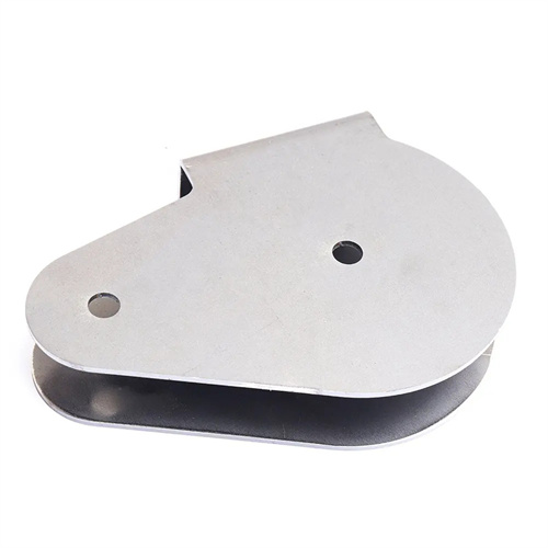
Design of simple side hole mold for pump cover
The design of the simple side flanging die for pump cover is an economical solution for the flanging of the side holes of pump cover parts. It is suitable for small and medium-sized batch production and is widely used in agricultural machinery, water pump manufacturing and other fields. Compared with complex multi-station molds, simple flanging molds have the characteristics of simple structure, low manufacturing cost and convenient debugging, but their design needs to simplify the structure under the premise of ensuring processing accuracy. At the beginning of the design, the material thickness of the pump cover (usually 4-8mm gray cast iron or steel plate), the diameter and height of the flanging hole need to be clarified. For example, for a flanging hole with a diameter of 20mm, the diameter of the prefabricated hole needs to be calculated (generally 0.7-0.8 times the diameter of the flanging hole) to ensure that the height after flanging reaches more than 5mm. At the same time, the space limitation on the side of the pump cover needs to be considered, and the mold outline size needs to be smaller than the distance from the side of the part to the adjacent structure to avoid interference.
The core structure of this mold consists of a die, a punch, a positioning device, and a manual clamping mechanism. The die is made of 45 steel and, after tempering, reaches a hardness of HRC 28-32. The working surface is milled with a positioning plane that aligns with the side of the pump cover, with a flatness error controlled within 0.05mm/m. The punch is designed according to the size of the flanging hole. The head diameter is equal to the inner diameter of the flanging hole, and the corner radius is 0.5-1 times the material thickness. For example, for a 5mm thick steel plate, the corner radius is set to 3mm to reduce material tearing during flanging. The positioning device uses a combination of a locating pin and a support block. The locating pin inserts into a prefabricated hole in the pump cover for radial positioning, while the support block absorbs the axial force during flanging to prevent deformation of the pump cover. The manual clamping mechanism uses a lever-type structure. A handle drives the pressure block to press the pump cover against the die. The clamping force is adjusted by adjusting the spring preload, generally controlled at 5-10kN.
Calculating the force parameters during the punching process is crucial for ensuring die reliability. The punching force can be calculated using the formula F = 1.1πtσb (D – d), where t is the material thickness, σb is the tensile strength, D is the punching diameter, and d is the prefabricated hole diameter. For example, using 6mm thick Q235 steel plate (σb = 400MPa), with a punching diameter of 30mm and a prefabricated hole diameter of 22mm, the calculated punching force is approximately 15kN. Therefore, the die’s load-bearing components require strength verification. For example, the minimum punch diameter must be greater than 12mm to prevent bending and fracture. Furthermore, the material flow characteristics during the punching process must be considered, and the edges of the prefabricated hole must be chamfered (0.5×45°) to reduce stress concentration and prevent cracking. For brittle materials such as gray cast iron, annealing is required before punching to reduce the hardness to below HB180 and improve the material’s plasticity.
The guide and limit design of the mold is simplified but indispensable. A sliding guide method is adopted, and a guide sleeve is set between the punch and the die base. The matching clearance is controlled at 0.05-0.1mm to ensure the smooth movement of the punch. The limit device adopts a bolt adjustment structure. The height of the hole is controlled by adjusting the extension length of the limit bolt. For example, when the hole height needs to be 6mm, the limit bolt is adjusted to the punch to contact the die after it goes down 6mm to prevent overpressure from causing deformation of the parts. The mold is installed by a combination of T-slot and pressure plate. The die is fixed on the workbench of the press, and the punch is connected to the slide of the press through the die handle. During installation, it is necessary to ensure that the axis of the punch is perpendicular to the positioning plane of the die, and the verticality error does not exceed 0.1mm/100mm.
The debugging and maintenance of this simple mold are unique. When testing the mold, first place the pump cover on the die, manually press it and then perform a single punching. Measure the height and verticality of the hole. If the height is insufficient, the limit bolt can be shortened. If the verticality is out of tolerance, the installation position of the die needs to be adjusted. The wrinkles on the edge of the hole can be solved by grinding the fillet of the punch, for example, increasing the fillet radius from 2mm to 3mm to improve material flow. During use, the wear of the punch needs to be checked every 50 pieces. When the head diameter wear exceeds 0.1mm, chrome plating repair is required (chrome plating thickness 0.05 – 0.1mm). In terms of maintenance, the iron filings on the working surface of the mold need to be cleaned every week, and anti-rust oil should be applied to prevent rust. The mating surfaces of the locating pin and the guide sleeve need to be regularly filled with lubricating oil to ensure flexible operation. Although the mold is simple, through reasonable design and maintenance, the tolerance of the hole size can be controlled within ±0.2mm, and the verticality error does not exceed 0.15mm, which meets the assembly requirements of the pump cover.