Design of bending die for V and U-shaped parts
The design of bending dies for V and U-shaped parts is an important part of sheet metal stamping processing and is widely used in automobile manufacturing, mechanical processing, electronic equipment and other industries. As common bending parts, V-shaped and U-shaped parts have relatively simple structures, but the design quality of the bending die directly affects the dimensional accuracy, shape accuracy and production efficiency of the parts. In the early stage of design, the material properties of the bending parts, such as the yield strength, tensile strength, elongation, etc. of the material, must be fully considered. These parameters determine the degree of deformation and the required bending force during the bending process. For example, for high-strength steel plates, the yield strength is higher, and a greater bending force is required when bending, and springback is prone to occur. Therefore, corresponding measures must be taken in the mold design to control springback.
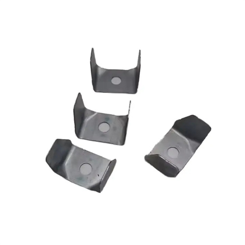
The structural design of the bending die needs to be determined according to the specific shape and size of the V-shaped and U-shaped parts. The V-shaped bending die usually consists of a punch, a die, a positioning device and a discharge device. The shape of the punch is consistent with the inner shape of the V-shaped part, and the angle of the die needs to be adjusted according to the springback of the bent part . It is generally 1° – 3° smaller than the angle required by the part to compensate for the springback. The structure of the U-shaped bending die is relatively complex. In addition to the punch and die, a press plate is also required to prevent the sheet from deflecting and wrinkling during the bending process. The pressure of the press plate needs to be moderate. If the pressure is too small, it will not have a pressing effect. If the pressure is too large, it will increase the wear and bending force of the mold. For the die of the U-shaped part, the gap on both sides should be consistent, generally 1.05 – 1.1 times the thickness of the sheet, to ensure the dimensional accuracy on both sides of the bent part.
The design of the positioning device is crucial for ensuring the bending accuracy of V- and U-shaped parts. V-shaped parts are typically positioned using stop pins or positioning plates. The positioning method is determined based on the part’s size and shape to ensure accurate positioning of the sheet metal during the bending process. For U-shaped parts, since both sides must be bent, the positioning device must simultaneously maintain both the front-to-back and left-to-right positioning of the sheet metal. This can be achieved by combining positioning pins and plates, or by using guide pins and holes, to improve positioning accuracy. The working surface of the positioning device must be smooth to avoid scratching the sheet metal surface, and the positioning components must possess sufficient strength and wear resistance to ensure long-term stability.
The calculation of bending force is an important part in the design of bending dies for V and U-shaped parts. It directly affects the selection of stamping equipment and the strength design of the die structure. The calculation formula for the bending force of V-shaped parts is: F = k * B * t² * σb / (r + t), where F is the bending force, k is the safety factor, B is the sheet width, t is the sheet thickness, σb is the tensile strength of the material, and r is the bending radius. The calculation of the bending force of U-shaped parts needs to consider the pressing force, and the total bending force is the sum of the bending force and the pressing force. When calculating the bending force, it is necessary to select appropriate parameters according to the actual situation to ensure the accuracy of the calculation results. At the same time, the structural strength of the mold must meet the requirements of the bending force to avoid deformation or damage to the mold during the stamping process.
Springback control is a difficult problem in the design of V- and U-shaped bending dies. Since the material will produce elastic deformation during the bending process, when the bending force is removed, the part will rebound to a certain extent, resulting in changes in the angle and size of the part. In order to control the springback, a variety of measures can be taken, such as setting a springback compensation angle on the die, making the angle of the die slightly smaller than the angle required by the part, and using the elastic deformation of the die to compensate for the springback of the part; or using the correction bending method to increase the pressure in the later stage of bending and reduce the proportion of elastic deformation. In addition, it is also important to choose a suitable bending radius. A bending radius that is too small will cause the part to crack, and a too large bending radius will increase the amount of springback. Generally, the bending radius should be greater than 1-2 times the thickness of the material. At the same time, for materials with thicker thickness or higher strength, heating bending can be used to reduce the yield strength of the material and reduce springback.