Design of main parts of blanking die
The design of a blanking die’s key components is crucial for its overall performance. These include the punch, die, die frame, positioning mechanism, and discharge mechanism, among other key elements. Each component must be designed with a balance of functionality, cost-effectiveness, and reliability. These components work together to complete the blanking and separation process, so a holistic approach is crucial during design, ensuring parameter matching and coordinated operation between components. For example, the gap accuracy between the punch and die, the accuracy of the positioning mechanism, and the flexibility of the discharge mechanism all directly impact the quality of the blanked part and the lifespan of the die.
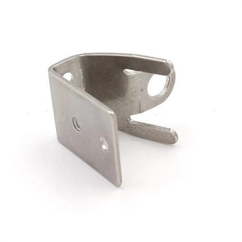
As a part that directly contacts and acts on the sheet metal, the design of the punch needs to focus on strength, rigidity, and cutting edge sharpness. The structural form of the punch can be divided into round, special-shaped, and complex shapes according to the shape of the blank. Circular punches usually adopt a stepped structure with a tail diameter larger than the working part to enhance overall rigidity; special-shaped punches need to be designed according to the contour of the part, and if necessary, reinforcing ribs or sheath structures should be used to prevent bending or breaking during stamping. The length of the working part of the punch needs to be reasonably determined, generally 2-4 times the thickness of the sheet metal plus the thickness of the stripper plate, to ensure stable force transmission during the stamping process without excessive deformation. In terms of material selection, punches are often made of high-strength alloy tool steels such as Cr12MoV and high-speed steel. After quenching, the hardness reaches HRC58-62 to ensure sufficient wear resistance and impact resistance.
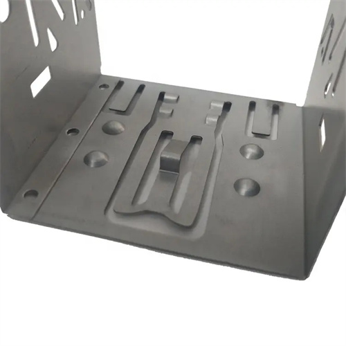
The design of the die complements the punch, and its structure is determined by the material removal method, part shape, and production batch. A one-piece die is suitable for small, simple parts, offering a compact and high-strength design. A segmented die is suitable for large or complex parts, dividing the die into smaller pieces to reduce machining complexity and conserve precious materials. Die cutting edges come in two types: flat and beveled. Flat edges offer high blanking force but high precision, making them suitable for precision parts. Beveled edges reduce blanking force and are suitable for thick sheet metal or large parts. The die’s discharge holes must be designed to ensure smooth discharge of waste. The hole diameter should be 3-5mm larger than the punch diameter. For long, strip-shaped waste, stepped discharge holes or inclined discharge channels can be used to prevent waste blockage. Similar to the punch, the die material selection requires high hardness and wear resistance. Furthermore, considering processability, complex die shapes can be machined using electrospark forming or wire cutting.
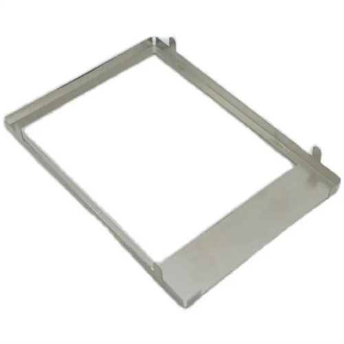
The die frame, the foundational support component of the mold, consists of an upper die base, a lower die base, guide pins, and guide bushings. Its design must ensure sufficient rigidity and guiding accuracy. The upper and lower die bases are typically made of cast iron or cast steel. Their thickness, determined by the mold size and blanking force, is generally 50-200mm. Large molds require reinforcing ribs to prevent deformation. The precision of the fit between the guide pins and guide bushings directly affects the uniformity of the gap between the punch and die. A clearance fit of H7/H6 is typically used. The guide pins must be long enough to ensure a sufficient guide length of 10-15mm for the guide bushing when the mold is closed. Guide pins can be arranged diagonally or in a square pattern. For large molds, a square pattern with additional guide pins is recommended for improved guiding stability. The die frame’s mounting base surface must be ground to a flatness tolerance within 0.02mm/100mm to ensure a good fit with the press worktable.
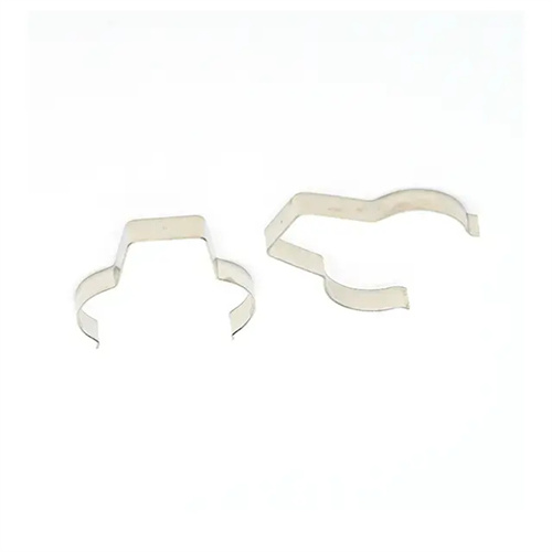
The design of the positioning device and the unloading device needs to be optimized according to the production method and part precision requirements. The stop pins, guide plates and other parts in the positioning device must ensure that the positioning accuracy is within ±0.05mm. For precision blanking parts, a combination of side blades and guide pins should be used for positioning to control the positioning error to ±0.01mm. The design of the unloading device must take into account both the unloading force and the protection of the workpiece. The spring selection of the elastic unloading device must be calculated based on the unloading force to ensure that the elastic force is uniform and sufficient; the rigid unloading device must ensure the parallelism of the unloading plate and the die to avoid bending and deformation of the workpiece. For the blanking die in the automated production line, it is also necessary to design automatic positioning and unloading components that match the feeding mechanism to realize unmanned production. By systematically designing the main components, it can be ensured that the blanking die can stably output high-quality blanking parts while producing efficiently.