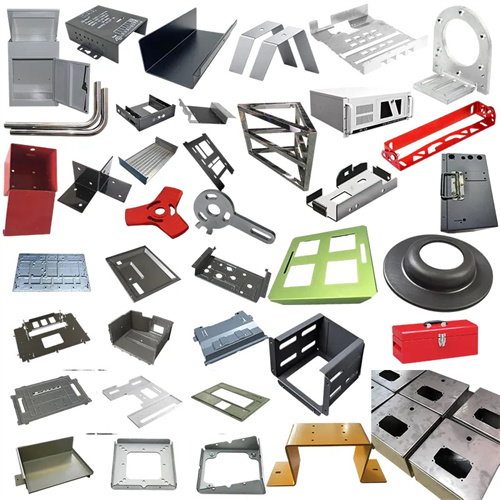
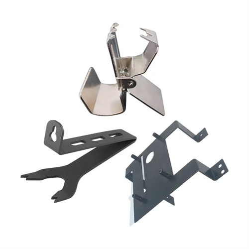
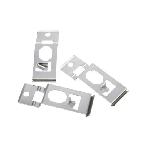
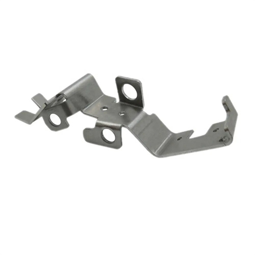
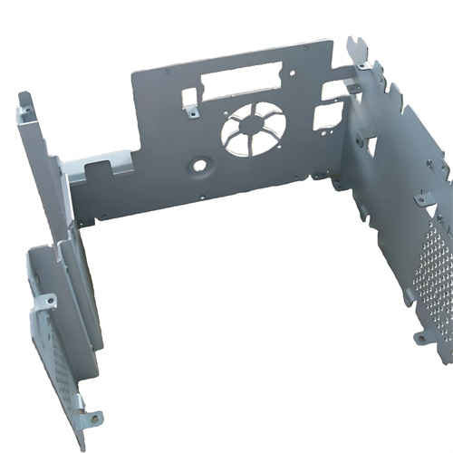
Determination of Reasonable Clearance Value of Blanking Die
Determining the proper clearance value for the punching die is crucial for ensuring the quality of the blanked parts, reducing the blanking force, and extending the life of the die. The blanking clearance, typically expressed as a bilateral gap, refers to the distance between the punch and die cutting edges. Its size directly affects stress distribution, material deformation, and fracture separation during the blanking process. A reasonable clearance value ensures that cracks at the punch and die cutting edges meet smoothly, resulting in a smooth cross-section, minimal burrs, and high dimensional accuracy, while also reducing die wear. Determining the proper clearance value requires comprehensive consideration of the material type, thickness, and properties, as well as the quality requirements for the blanked parts, and is carried out through a combination of theoretical calculations and practical experience.
Material thickness is the primary factor in determining the blanking clearance. Generally speaking, the thicker the material, the larger the required blanking clearance. This is because when blanking thick sheet metal, the plastic deformation zone is wider, and the crack propagation path is longer, requiring a larger clearance to ensure smooth abutment between the upper and lower cracks. For common materials such as mild steel, the clearance value is typically 5%-15% of the sheet thickness. The specific value is determined based on the thickness of the sheet: when the sheet thickness t≤1mm, the clearance value is 5%-8%t; when 1mm<t≤3mm, the clearance value is 8%-12%t; and when t>3mm, the clearance value is 12%-15%t. For example, for a 2mm thick mild steel sheet, the ideal bilateral clearance value should be 0.16-0.24mm. Punching within this range provides optimal cross-section quality and minimizes burrs.
The properties of the material have a significant impact on the choice of gap value. Plastic materials require smaller gaps, while brittle materials require larger gaps. When punching plastic materials such as low carbon steel, copper, and aluminum, the plastic deformation is sufficient, the tensile and compressive deformation of the material at the cutting edge is large, and the smaller gap can make the plastic deformation uniform, the width of the bright band increases, and the fracture zone is smooth. When punching brittle materials such as high carbon steel and cast iron, the plastic deformation is small and cracks occur early. A larger gap is required to reduce the extrusion of the material and avoid interlayers and secondary shearing in the cross section. For example, when punching high carbon steel, the gap value can be increased by 20%-30% compared with low carbon steel of the same thickness to ensure smooth crack expansion and obtain a smoother cross-section.
The quality requirements of the blanked part are a key factor in determining the clearance value. For parts requiring high cross-sectional quality and minimal burrs, a smaller clearance value should be used. For parts requiring high dimensional accuracy, the appropriate clearance direction should be selected based on the part type (blanking or punching). During blanking, the die size determines the part’s overall dimensions, so a smaller clearance should be used to keep the part’s dimensions close to the die size. During punching, the punch size determines the hole size, so a smaller clearance should be used to keep the hole’s dimensions close to the punch size. Precision blanked parts typically require a bright band width exceeding 80% of the plate thickness. In this case, the clearance value should be controlled to 1%-3% of the plate thickness, and a counter-pressure device should be used to achieve pure shear deformation of the material and avoid the formation of fracture bands.
The main methods for determining clearance values include theoretical calculation, empirical data, and trial punching adjustment. The theoretical calculation method uses mechanical analysis to determine the appropriate clearance value based on the material’s shear strength and sheet thickness. The formula is: Z = 2tτ/(σb + τ), where Z is the double-sided clearance, t is the sheet thickness, τ is the material’s shear strength, and σb is the material’s tensile strength. This method is more accurate, but requires accurate material properties and is suitable for applications requiring high precision. The empirical data method determines clearance values based on empirical tables or formulas derived from long-term production practice. This method is simple and practical, and widely used in actual production. For example, the recommended clearance values for various materials are provided in the “Stamping Manual.” The trial punching adjustment method uses test punches to adjust the clearance value based on cross-sectional quality and dimensional accuracy. This method is suitable for punching new materials or parts with complex shapes. During trial punching, the clearance can be adjusted by adding or removing shims or refining the cutting edge until satisfactory results are achieved.
Die life is also a factor to consider when determining the clearance value. A reasonable clearance can reduce wear on the die cutting edge and extend die life. If the clearance is too small, friction between the die and the material is intense, easily wearing the cutting edge. This also increases blanking forces and the load on the die, leading to premature die failure. If the clearance is too large, bending and tensile deformation of the material increases, increasing the impact forces on the cutting edge and shortening the die life. Research has shown that a clearance of 10%-12% of the plate thickness minimizes die wear and maximizes die life. Therefore, when determining the clearance value, it is important to consider die life while ensuring the quality of the blanked part, choosing a reasonable clearance value that balances quality and life.