Blanking die ejector device
The ejector device of a punching die is an important component that ensures the smooth release of the punched part from the die. Its main function is to promptly eject the workpiece or scrap stuck in the die or punch after the punching process is completed, so as to avoid affecting the next stamping cycle. The performance of the ejector device is directly related to production efficiency and the surface quality of the punched part. During design, it is necessary to select the appropriate ejection method and power source based on the shape, size, material, and structural characteristics of the punched part. Common ejector devices include elastic ejectors, rigid ejectors, pneumatic ejectors, and hydraulic ejectors, each with its own unique application scenarios and working characteristics.
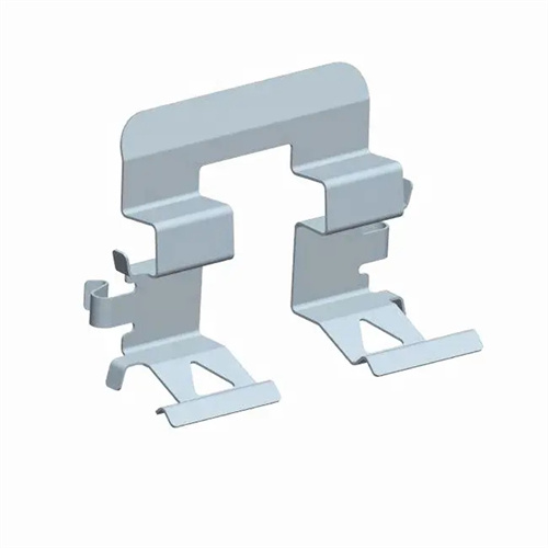
The elastic ejector is the most widely used ejection method in blanking dies. It relies on the elastic force of a spring or rubber to achieve ejection, offering advantages such as a simple structure, low cost, and easy installation. The device typically consists of an ejector pin, an ejector plate, a spring (or rubber), and a stop screw. After the punch descends to complete the blanking process, the upper die rises, and the restoring force of the spring or rubber pushes the ejector plate and ejector pin, ejecting the workpiece from the die. The ejection force of the elastic ejector can be adjusted by adjusting the compression of the spring or replacing it with a spring of varying stiffness. It is suitable for ejecting small and medium-sized blanking parts and thin materials. However, due to elastic fatigue of the spring and rubber, the ejection force gradually decreases after long-term use. Therefore, regular inspection and replacement are required to ensure consistent ejection performance. Furthermore, the elastic ejector’s high ejection speed can cause workpiece deformation due to the excessive impact force on easily deformed thin-walled parts, necessitating the use of a cushioning pad at the contact point between the ejector plate and the workpiece.
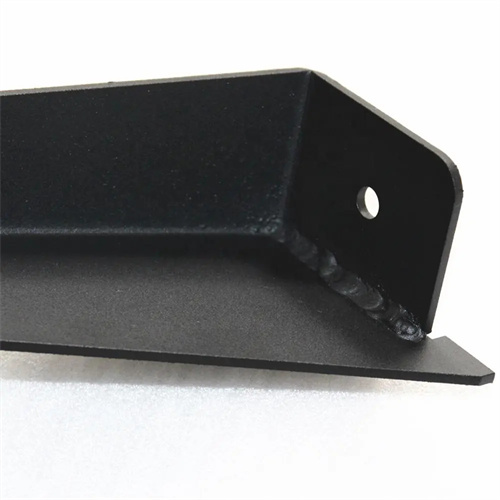
The rigid ejector device achieves ejection through mechanical transmission, with large and stable ejection force, and is suitable for ejecting large, thick-walled blanking parts or workpieces with complex shapes. Its typical structure includes an ejector rod, an ejector plate, a cam mechanism, or a lever mechanism. The movement of the slide of the press is used to drive the ejector rod upward through the transmission components to eject the workpiece. The ejection stroke and ejection force of the rigid ejector device can be precisely controlled, and the ejection action is strictly synchronized with the stamping process, avoiding the uncertainty of elastic ejection. For example, in large blanking dies, a rigid ejector mechanism installed under the worktable of the press is often used. The ejector rod is driven by the connecting rod of the press to ensure that heavy workpieces can be smoothly separated from the die. However, the rigid ejector device has a complex structure and needs to be linked with the moving parts of the press. It is difficult to manufacture and debug, and the ejection speed is slow, making it unsuitable for high-speed stamping applications.
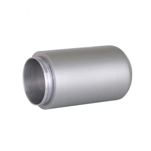
Pneumatic ejection devices are powered by compressed air, using a cylinder to drive an ejector rod to achieve ejection. They feature fast response, adjustable ejection force, and flexible installation. The device consists of a cylinder, ejector rod, air pipe, and control valve. Cylinders of different diameters can be selected based on the size of the part being punched, and the ejection force is controlled by adjusting the air pressure (typically 0.4-0.6 MPa). The ejection stroke of the pneumatic ejection device can be precisely controlled using the cylinder’s stroke adjustment nut, and the ejection action is smooth, effectively protecting the surface quality of the part. It is particularly suitable for precision punches requiring high surface finish. In continuous punching dies, the pneumatic ejection device can be linked to the feeding mechanism to achieve automated production and improve production efficiency. However, its disadvantages are that it requires a compressed air system, and the ejection force is significantly affected by air pressure fluctuations, which can lead to insufficient ejection force for large workpieces.
The hydraulic ejector device is suitable for heavy-duty blanking dies that require a large ejection force. It uses the pressure of the hydraulic oil to drive the hydraulic cylinder, providing strong and stable power for the ejection action. The hydraulic ejector device consists of a hydraulic cylinder, a push rod, a hydraulic pump, a relief valve, etc. The ejection force can be steplessly controlled by adjusting the pressure of the hydraulic system (generally 5-20MPa), and the ejection stroke can be accurately monitored by a displacement sensor. In thick sheet metal blanking dies, the hydraulic ejector device can easily eject heavy workpieces stuck in the die, avoiding damage to the mold caused by poor ejection. In addition, the ejection speed of the hydraulic ejector device can be adjusted by a flow control valve to achieve slow and smooth ejection, which is suitable for large blanking parts that are easily deformed. However, the device has a complex structure and high manufacturing cost. In addition, there is a risk of oil leakage in the hydraulic system, which makes maintenance difficult. It is usually used in occasions with special needs.
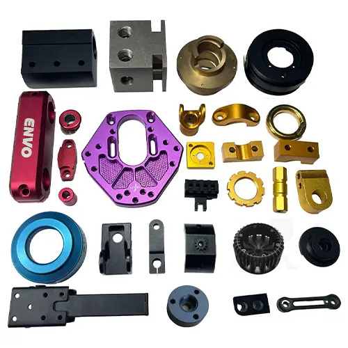
The design of the ejector device must meet the requirements of sufficient ejection force, smooth movement, and accurate positioning, while also considering coordination with other parts of the mold. The number and distribution of ejector pins should be evenly arranged according to the shape of the blank to ensure uniform distribution of ejection force and avoid tilting or deformation of the workpiece during ejection. The clearance between the ejector pin and the die should be controlled within the range of 0.02-0.05mm to ensure flexible movement of the ejector pin and prevent material leakage. For blanking parts with flanges or special shapes, the ejector device should be designed to match the contour of the workpiece to increase the contact area and improve the stability of the ejection. In addition, the ejector device needs to be equipped with a limiting mechanism, such as a limit block or a limit screw, to prevent damage to the ejector pin due to excessive ejection. By rationally designing the ejector device, the blanking process can be ensured to be continuous and stable, improving production efficiency and the quality of blanking parts.
