Design of hinge roll mold
Hinge rolling dies are a key process for achieving the desired rounded shape of hinge blades. Widely used in applications such as door and window hardware and furniture fittings, they can roll steel sheets with a thickness of 0.3-2mm into tubular structures with a diameter of 3-10mm. The roundness error after rolling is less than 0.1mm, and the joint clearance is less than 0.2mm. The quality of hinge rolling directly impacts the hinge’s rotational flexibility and service life. The die design must address wrinkling, cracking, and dimensional instability during the rolling process. Initially, the neutral layer radius must be calculated based on the unfolded length and rolled diameter of the hinge blades. The formula is r = r + kt (r is the inner diameter of the rolled blade, k is the neutral layer coefficient, and t is the material thickness). For mild steel, k is set to 0.5-0.6 to ensure accurate length measurements after rolling.
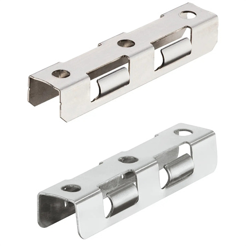
The die structure consists of a curling punch, a die, a positioning device, a material holding device, and a guide mechanism. The curling punch is constructed of Cr12MoV alloy tool steel, hardened to HRC 58-62, and the working surface polished to Ra 0.4μm or less. The punch diameter is 0.1-0.2mm smaller than the inner diameter of the curled element to allow for material springback. The die utilizes a stepped structure with two stations: pre-bending and final curling. The pre-bending station bends the blade end to a 45-90° angle, while the final curling station completes a 360° curl. The corner radius of each die station is designed to be 2-5 times the material thickness. For 1mm thick steel plate, the pre-bending radius is set at 2mm, and the final curling radius is set at 5mm, guiding the material’s gradual deformation.
Force control during the curling process requires precise matching of material properties. The total curling force is calculated using the formula F = K × L × t × σs (K is the coefficient, L is the curling length, t is the thickness, and σs is the yield strength). For a mild steel hinge with a length of 50 mm and a thickness of 1 mm, the curling force is approximately 3-5 kN. A spring or cylinder is used to provide power to ensure stable force. A pressure device is installed above the die and utilizes a polyurethane rubber pad (hardness 60-70 Shore A). The pressure is 10%-15% of the curling force to prevent material slippage during the curling process and ensure consistent curl diameter.
The positioning and guiding system ensures accurate curling. A stop pin is used for longitudinal positioning, positioned at a distance from the center of the curl equal to the effective length of the hinge blade, with an accuracy of ±0.1mm. Lateral guides are provided in the width direction, with a spacing 0.3-0.5mm greater than the blade width, allowing for slight material movement to relieve stress. The guiding mechanism utilizes ball guide pins and bushings with a diameter of 12-20mm and a clearance of 0.01-0.03mm, ensuring precise alignment of the punch and die during curling to avoid elliptical or eccentric shapes.
Continuous commissioning and batch production optimization are essential. During mold trials, measure the roll diameter using a dial indicator. Sample 10 pieces per batch. If the diameter deviation exceeds 0.1mm, adjust the punch diameter (by 0.05mm each time). Check the joint gap. If it is too large, increase the pressing force or adjust the die radius. If it is too small, reduce the roll force to prevent excessive material compression. During routine maintenance, clean iron filings from the die after every 1,000 pieces. Check the punch surface for wear and polish with fine sandpaper if scratches appear. For batch production, the mold can be integrated with an automatic feeding mechanism, using a servo motor to drive the feed at a speed of 10-20 pieces/minute. Sensors detect the presence of material, enabling fully automatic roll formation and improving production efficiency.