Design of Drawing Die for Step Drawing Parts
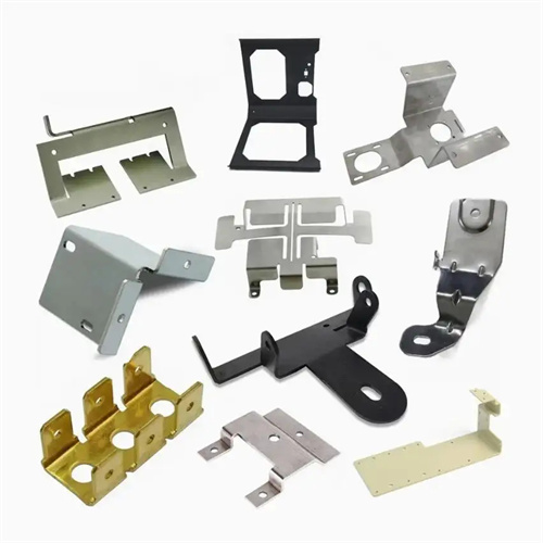
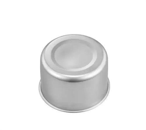
Step drawing die design is a forming technology for cylindrical parts with multiple, successively decreasing diameters. Widely used in applications such as motor housings, hydraulic cylinders, and multi-stage pump bodies, it can be drawn in one or more passes, ensuring coaxiality errors of less than 0.1mm between each step. The difficulty of drawing these parts increases with the number of steps. Initially, the number of draw passes should be determined based on the diameter ratio of each step (typically, a ratio of adjacent steps ≥ 1.2) and the material thickness (1-8mm). For parts with more than three steps, multiple draw passes are recommended, forming one or two steps at a time to avoid excessive stretching. For example, a three-step part (diameter φ100mm → φ80mm → φ60mm, height 120mm) made of 20-grade steel requires three draw passes: the first to φ80mm, the second to form the φ60mm steps, and the third to finalize the dimensions of each step.
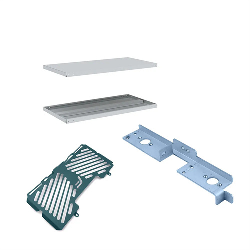
Die structures are categorized as single-step or progressive based on the number of draw cycles. Single-step dies are suitable for small and medium-volume production, while progressive dies are suited for large-scale production. A single-step step drawing die consists of a punch, die, blank holder, positioning device, and guide mechanism. The punch is designed based on the final shape of the stepped part. The corner radius of each step is 5 to 8 times the material thickness. For a 3mm thick part, the corner radius is set at 15 to 24mm to prevent cracking. The die is a split-piece structure, allowing each step to be independently replaceable. The material used is Cr12MoV, hardened to HRC 58 to 62, and the working surface is polished to Ra 0.4μm or less. The blank holder must cover the forming area of each step. A nitrogen spring is used to provide the blank holder force. The force is calculated based on the projected area of the largest step and is typically 20% to 30% of the drawing force. For a φ100mm step, the blank holder force is 15 to 25kN.
Drawing process parameters must be optimized in a step-by-step manner. The drawing coefficient for the initial drawing process is 0.55-0.65, increasing by 0.05-0.1 for each subsequent drawing process to ensure uniform plastic deformation of the material. The drawing speed is controlled between 50-100 mm/s. For high-strength materials (such as 45 steel), the speed is kept to the lower limit to avoid cracking caused by excessive deformation. For lubrication, high-viscosity drawing oil (viscosity 40-60 cSt) is used for the initial drawing process, while low-viscosity oil (20-30 cSt) can be used for subsequent drawing processes. This creates a uniform oil film (thickness 8-12 μm) on the die surface, reducing the friction coefficient to below 0.1. For viscous materials such as stainless steel, a boron nitride coating is sprayed on the blank surface to further reduce friction.
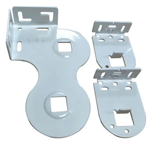
The positioning and guiding system must ensure the coaxiality of each step. Guide pins and bushings are used for guidance. The guide pins have diameters of 25-40mm and a clearance of 0.01-0.03mm to ensure accurate centering between the punch and die. The positioning device utilizes a combination of locating pins and stoppers. The locating pins are inserted into the positioning holes created in the previous step. The stoppers mate with the formed steps with a clearance of 0.05-0.1mm, ensuring an axial positioning accuracy of ±0.1mm. For large stepped parts (diameter > 200mm), an intermediate guide sleeve is required, positioned in the middle of the punch to enhance guiding stability.
Commissioning and maintenance require a step-by-step inspection process. During mold trials, measure the diameter, height, and wall thickness of each step. Five samples per step should be inspected. The diameter tolerance must be within ±0.15mm, and the wall thickness reduction must be less than 15%. If wrinkles appear on a step, increase the blank holder force in the corresponding area (by 5%-10%). If cracks appear, increase the transition radius of that step (by 1-2mm at a time). During routine maintenance, inspect the punch steps for wear every 2,000 units. Regrind if wear exceeds 0.05mm. Replace the die every 5,000 units to ensure forming accuracy. During storage, apply anti-rust oil to the punch surface and support it with a dedicated bracket to prevent deformation.