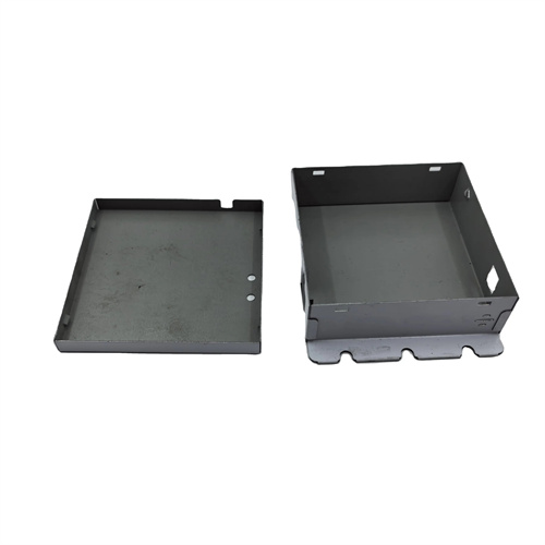
Design of the Drawing Die for Rectangular Cover
The design of a drawing die for rectangular lids is a forming technology for rectangular or square box lids, widely used in applications such as appliance housings, toolbox covers, and automotive trim. It achieves smooth corner radius, vertical sidewalls, and a flatness tolerance of less than 0.2 mm/m. It is suitable for materials with thicknesses of 0.5-5 mm, such as mild steel and aluminum alloy. Compared to the deep drawing of circular parts, the difficulty of deep drawing rectangular lids lies in uneven material flow (material accumulation at corners and wrinkling along straight edges). This challenge must be addressed by optimizing the die corner radius and blank holder force distribution. Initially, the relative corner radius (r/B, where r is the corner radius and B is the length of the short side) of the rectangular lid must be calculated. When r/B is less than 0.2, a higher blank holder force is required to prevent corner wrinkling. When r/B is greater than 0.3, the blank holder force can be reduced to minimize thinning along straight edges.
The mold structure consists of a punch, die, blank holder, ejector, and guide mechanism. The punch is designed to resemble a rectangular cover, with corner radii 0.1-0.2mm larger than the part’s requirements to allow for springback. The material used is Cr12MoV, hardened to HRC 58-62, and chrome-plated (0.01-0.03mm thick) for enhanced wear resistance. The die is a monolithic structure, constructed from Cr12 steel, hardened to HRC 55-58. The corner radius is 3-6 times the material thickness. For a 2mm thick part, the radius is set at 6-12mm to promote material flow toward the corners. The blank holder utilizes a zoned design, with the corners holding 15%-20% more force than the straight edges. This is achieved by adjusting the preload of the nitrogen spring. For example, if the straight edge holds 10kN, the corners are set at 11.5-12kN to minimize wrinkling.
The drawing process parameters must match the geometric characteristics of the rectangular cover. The drawing coefficient is 0.6-0.75. The longer the short side, the higher the drawing coefficient. For a rectangular cover with a short side of 100mm, the drawing coefficient is 0.7. The drawing speed is controlled at 30-80mm/s. For aluminum alloys, the speed can be increased to 60-80mm/s. For mild steel, the lower limit is used. For rectangular covers with a depth exceeding 0.8 times the short side length, multiple drawing passes are required. The initial drawing is to 50-60% of the depth, and subsequent drawing passes increase the depth by 20-30%. Annealing treatment (600-650°C for mild steel, 1 hour) is performed between passes to eliminate work hardening.
The positioning and ejection mechanism must be adapted to the characteristics of rectangular parts. Positioning utilizes a combination of guide plates and stop pins. The spacing between the guide plates is 0.1-0.2mm larger than the width of the blank, and the stop pins are positioned with an accuracy of ±0.1mm to ensure that the center of the blank aligns with the center of the mold. The ejection mechanism utilizes elastic ejector pins evenly distributed across the bottom of the die (one pin per 100mm of length). The ejection force is 10-15% of the drawing force, ensuring smooth ejection of the part after drawing to avoid deformation. For large rectangular covers (side length > 300mm), a lateral ejection mechanism is required to prevent the part from becoming stuck in the die.
During commissioning and quality control, attention should be paid to corner forming. During die trials, measure the thickness of the four corners (thickness increase must be less than 20%) and the perpendicularity of the straight edges (error <0.5mm/m). If the corners are too thick, reduce the die radius or increase the drawing speed. If the straight edges wrinkle, increase the straight edge blank holder force. Use a three-dimensional coordinate measuring machine to check part flatness, sampling 3-5 pieces per batch. If the tolerance is exceeded, adjust the parallelism of the punch and die (error <0.05mm/m). During routine maintenance, clean the die surface of oil and iron filings every 1,000 pieces, inspect the blank holder for wear, and polish any scratches with fine sandpaper to maintain a smooth surface finish.