Design of pipe cutting die
The design of pipe cutting die is a special die technology for precise cutting of various metal pipes (such as steel pipes, aluminum pipes, and copper pipes). It is widely used in automobile manufacturing, air conditioning and refrigeration industries, and can achieve burr-free cutting according to the material and diameter of the pipe (usually 10-150mm), and the verticality error of the cut surface is less than 0.1mm/m. Compared with sawing, laser cutting and other processes, die cutting has high efficiency (up to 50-150 pieces per minute) and can keep the inner diameter of the pipe without deformation, which is particularly suitable for mass production. In the early stage of design, the cutting force needs to be calculated according to the wall thickness of the pipe (1-8mm) and the material strength (such as 20 steel σb = 410MPa). The formula is F = πDδτ (D is the outer diameter of the pipe, δ is the wall thickness, and τ is the shear strength of the material), and a 20% safety factor is added. For example, for a steel pipe with a diameter of 50mm and a wall thickness of 4mm, the cutting force is about 80kN, and a press of more than 100kN needs to be selected.
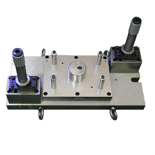
The die structure is divided into two parts: the upper die and the lower die. The core components include the cutting punch, the die, the V-shaped positioning block, the unloading device and the guide mechanism. The cutting punch is made of Cr12MoV alloy tool steel, with a quenching hardness of HRC58-62. The cutting edge adopts a bevel blade design with an angle of 5°-10° with the vertical line. Compared with the flat blade, it can reduce the cutting force by 40% and reduce the equipment load. The die adopts a split structure, which is composed of the left and right dies. The U-shaped groove is opened on the joint surface. The radius of the groove bottom is 0.1-0.2mm larger than the outer diameter of the pipe fitting to ensure the stable placement of the pipe fitting. The die material is Cr12, with a quenching hardness of HRC55-58. The edge clearance is 10%-15% of the wall thickness. For 4mm thick steel pipes, the clearance is set to 0.4-0.6mm, which can effectively reduce cutting burrs.
The positioning and guiding system must ensure the cutting accuracy. The V-shaped positioning block is made of HT300 cast iron, surface hardened HRC40 – 45, the V-shaped groove angle is 90°, and the wear-resistant alloy sheet (such as ZGMn13) is installed at the bottom of the groove. The height of the positioning block can be fine-tuned by adjusting the bolt (range ±2mm) to ensure that the axis of the pipe is parallel to the cutting edge. The guiding mechanism adopts double guide pillars and guide sleeves, the guide pillar diameter is 25 – 40mm, the matching clearance is 0.01 – 0.03mm, and the guide pillar surface is chrome-plated to improve wear resistance. For large-diameter molds with a diameter of more than 100mm, auxiliary guide pillars need to be added and arranged at the four corners of the mold to further improve the guiding accuracy.
The anti-deformation design of the cutting process is the key. An elastic support block is set at the bottom of the U-shaped groove of the die. It is made of polyurethane rubber (hardness 80 Shore A). The height of the support block is 0.5-1mm higher than the bottom of the groove. Pre-pressure is applied to the bottom of the pipe during cutting to prevent radial collapse. For thin-walled pipes (wall thickness <2mm), a polyurethane core rod can be inserted into the pipe. The diameter of the core rod is 0.1-0.2mm smaller than the inner diameter of the pipe to avoid wrinkles on the inner wall during cutting. In addition, the stroke of the cutting punch needs to be precisely controlled, and the bottom dead point position is 0.5-1mm lower than the outer diameter of the pipe to ensure complete cutting while avoiding rigid collision between the punch and the die.
During debugging and maintenance, attention should be paid to the management of the cutting edge. During the mold test, a dial indicator is used to measure the verticality of the cut surface. Ten pieces are sampled for each batch. When the error exceeds 0.1mm/m, the gap between the concave mold and the die needs to be adjusted (adjustment amount ±0.05mm). The cutting edge is ground once every 2,000 operations, and a diamond grinding wheel (120# grain size) is used to ensure the sharpness of the cutting edge. After grinding, the burrs on the cutting edge need to be removed to avoid tearing of the pipe fittings during cutting. For materials that are easy to stick to the mold, such as copper tubes, copper-based grease (containing graphite) needs to be applied to the cutting edge every 500 operations to reduce friction and wear. When the mold is stored for a long time, anti-rust oil needs to be applied to the cutting edge surface, and grease needs to be injected into the guide pin and guide sleeve to prevent rust.