Design of the Compound Die for Drawing, Forming and Blanking of Square Box
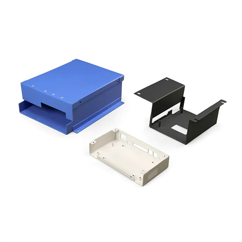
The design of a composite die for drawing, forming, and blanking square boxes is an integrated forming technology for rectangular or square box parts. It can complete the three key processes of blanking, drawing, and shaping in a single stamping stroke. It is widely used in applications such as appliance housings, tool boxes, and electronic device casings. These parts typically require smooth corner radius, vertical sidewalls, and a flat bottom. Therefore, the die design must address issues such as uneven material flow, corner thickening, and sidewall springback. Initially, the drawing coefficient is calculated based on the box’s dimensions (e.g., 100mm × 80mm), height (30-50mm), material thickness ( 1-3mm), and material type (e.g., Q235, 304 stainless steel). The initial drawing coefficient is generally 0.6-0.65. If the ratio of the box’s height to its minimum side length exceeds 0.8, multiple draw cycles may be considered. However, composite dies are generally suitable for shallow square boxes that can be formed in a single draw.
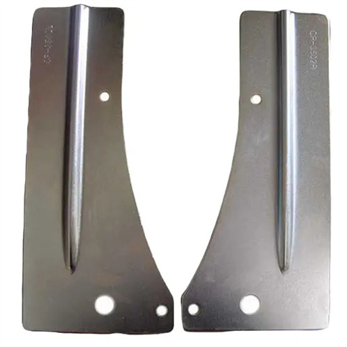
The mold structure adopts an inverted layout of “upper die blanking die + lower die convex die”. The core components include blanking punch, drawing punch, forming die, blank holder and unloading device. The blanking punch and drawing punch are integrated and made of Cr12MoV alloy tool steel. After quenching, the hardness reaches HRC58-62. The blanking cutting edge needs to be sharp, and the gap with the die is 8%-12% of the material thickness to ensure that there is no burr on the edge of the blanking part. The four corners of the drawing punch are the key parameters. The radius of the corners is 1.2-1.5 times the radius of the box body. For example, if the box body requires R5mm, the punch corner is set to R6-7.5mm to reduce the accumulation of corner materials. The forming die adopts a split structure, which consists of four side modules and the bottom, which is convenient for adjusting the verticality of the side wall. The module material is made of cemented carbide (WC-Co) to improve wear resistance, and the bottom is made of 45 steel quenched and tempered to ensure support rigidity.

The blanking and unloading systems need to accurately control the force distribution. The blanking ring is elastically driven (nitrogen spring or disc spring), and the blanking force is calculated according to the formula F = K×L×t×σs (K is the coefficient, L is the circumference of the square box, t is the thickness, and σs is the yield strength). For a Q235 square box of 100mm×80mm×0.8mm, the blanking force is usually 8-12kN, and the blanking force at the four corners needs to be slightly greater than that of the side wall (increase of 10%-15%) to prevent wrinkling at the corners. The unloading device consists of a stripper plate and an ejector. The stripper plate moves with the upper die. After the stamping is completed, the blank is unloaded from the blanking punch. The ejector is driven by the lower die spring to eject the formed square box from the drawing die. The ejection force is 30%-40% of the blanking force to ensure smooth demolding.

Material flow control is achieved through mold surface treatment and lubrication. The working surfaces of the drawing punch and die need to be polished to less than Ra0.2μm to reduce material flow resistance. Shallow oil grooves (2mm wide and 0.5mm deep) can be opened in the four corners to store drawing oil (viscosity 30 – 50cSt) to form a continuous oil film during the stamping process. For materials with strong viscosity such as stainless steel, extreme pressure grease (containing molybdenum disulfide) needs to be sprayed on the surface of the blank to reduce the friction coefficient to less than 0.1. In addition, the edge of the blank after blanking needs to be deburred (burr height <0.05mm) to avoid scratches on the side wall due to rough edges during drawing.
Debugging and optimization should be carried out in stages. During mold trials, the blanking process should be debugged separately to ensure that the dimensional tolerance of the blanked parts is within ±0.1mm. Then, deep drawing and forming are debugged. Forming quality is assessed by measuring the thickness of the box body’s four corners (thickness increase must be less than 15%) and the sidewall perpendicularity (error less than 0.5mm/m). If corner cracking occurs, the punch radius should be increased or the drawing speed should be reduced. If sidewall springback occurs, a negative angle compensation of 0.5°-1° can be set on the die sidewall. During routine maintenance, the mold surface should be cleaned of oil and metal debris every 1,000 pieces produced. The blanking cutting edge should be inspected for wear and reground if the cutting edge radius exceeds 0.1mm. The drawing punch should be polished every 5,000 pieces to maintain the required surface roughness.