End drawing die design
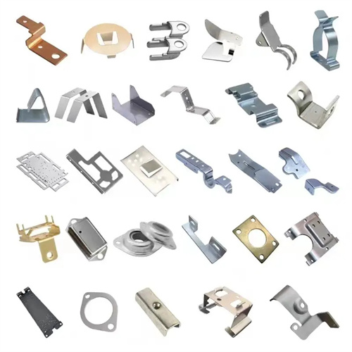
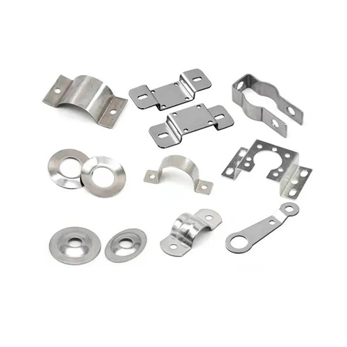
End drawing die design is a die technology for deep drawing of parts. It is mainly used to draw flanges, cups or other complex shapes at the ends of flat or cylindrical parts. It is widely used in automotive parts, electronic components, medical devices and other fields. Unlike overall drawing, end drawing only forms local areas of parts, so the die design needs to focus on solving the uniformity of local deformation and coordination with other parts of the parts. In the early stage of design, the number of drawing times and the drawing coefficient need to be determined according to the drawing dimensions (such as diameter, height) of the end of the part, the thickness of the original material and the material properties. The first drawing coefficient is generally 0.55-0.65, and the subsequent drawing coefficient is gradually increased to ensure that the material is uniformly deformed in each drawing. For example, a cup-shaped structure with a diameter of 50mm and a height of 30mm is drawn at the end of a low-carbon steel flat part with a thickness of 2mm. The diameter and height after the first drawing need to be calculated. If they do not meet the requirements, a second drawing is required.
The mold structure consists of a punch, a die, a blank holder, a positioning device and a guide device. The material of the punch and die is Cr12MoV alloy tool steel. After quenching, the hardness reaches HRC58-62, and the working surface is polished to Ra0.4μm or less to reduce the friction resistance during the drawing process. The radius of the corner of the die is determined according to the material thickness, generally 5-8 times the material thickness. For materials with a thickness of 2mm, the radius of the corner can be set to 10-16mm to facilitate the smooth flow of the material into the die. The design of the blank holder is particularly important. Its function is to prevent the material from wrinkling during the drawing process. The blank holder force needs to be calculated based on the drawing area and material thickness, usually 20%-30% of the drawing force, which can be provided by a spring or air cushion. For local end drawing, the blank holder needs to be designed to fit the non-drawing area of the part, and only the material of the drawing part is pressed to avoid affecting other parts of the part.
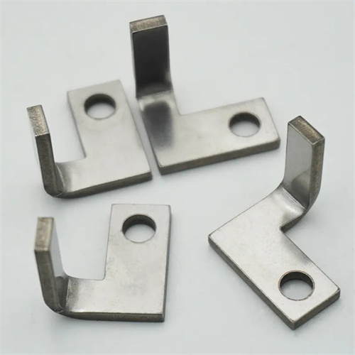
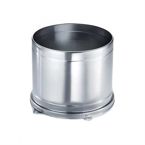
The positioning device needs to be designed according to the overall shape and size of the part to ensure the accurate end drawing position. If the part is flat, a combination of positioning pins and positioning plates can be used for positioning. The positioning pins are inserted into the prefabricated holes of the part, and the positioning plates limit the plane position of the part. The positioning accuracy is controlled within ±0.1mm. If the part is cylindrical, a combination of internal and external positioning can be used. The internal positioning mandrel is inserted into the interior of the cylindrical part, and the external positioning ring limits the radial position of the part to ensure that the coaxiality error between the drawing part and the axis of the part does not exceed 0.05mm. The working surface of the positioning device must be smooth to avoid scratching the surface of the part. For parts with high surface quality requirements, the surface of the positioning device needs to be chrome-plated with a coating thickness of 0.01-0.03mm and a hardness of HV800 or above.
Material flow control during the drawing process is a difficult point in the design of end drawing dies. Since only the end of the part is drawn, the flow of the material is constrained by other parts of the part, and local uneven deformation is prone to occur. Therefore, it is necessary to set a process cut or process hole on the die to allow excess material to flow and reduce drawing stress. The position and size of the process cut need to be determined by finite element simulation. It is generally opened at the edge of the drawing part with a length of 5-10mm and a width of 1-2mm to alleviate material accumulation. For multiple end drawing, the die size of each drawing needs to be reasonably designed to ensure that the shape of the previous drawing provides sufficient deformation space for subsequent drawing to avoid cracking. In addition, the drawing speed needs to be controlled at 50-100mm/s. For high-strength materials, the drawing speed can be appropriately reduced to reduce the material’s resistance to plastic deformation.
The debugging and maintenance of the mold require attention to details. When testing the mold, first use a blank of the same material as the part for trial drawing, check the dimensional accuracy and surface quality after drawing. If wrinkles occur, increase the blank holder force; if cracks occur, increase the radius of the die corner or reduce the drawing deformation. Use a three-coordinate measuring instrument to detect the dimensions of the drawing part to ensure that the diameter tolerance is controlled within ±0.1mm and the height tolerance is ±0.2mm. In daily maintenance, the oil and metal debris on the surface of the mold need to be cleaned every 800 times, and the wear of the punch and die needs to be checked. When the wear of the fillet radius exceeds 0.3mm, it needs to be repaired. The guide device needs to be regularly filled with grease, and the matching clearance between the guide column and the guide sleeve is controlled at 0.01-0.03mm to ensure smooth movement of the mold and avoid excessive part size due to guide deviation.