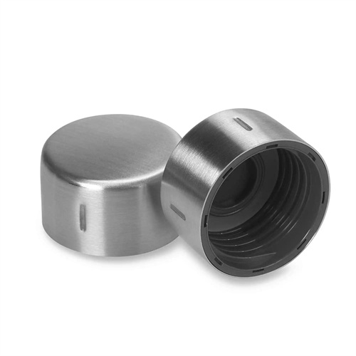
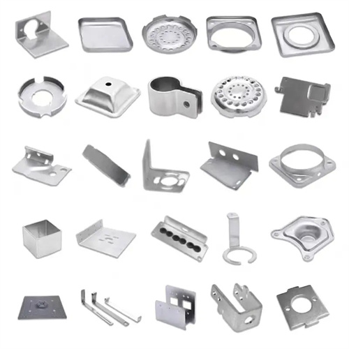
Punching and blanking compound die design
Punching and blanking compound die design is a common and efficient forming technology in stamping dies. It can complete the punching and blanking processes in one stamping stroke, reduce process flow, improve the dimensional accuracy and production efficiency of parts, and is widely used in the processing of various flat parts, such as gaskets, cover plates, etc. Compared with single-process dies, the structure of compound dies is more complicated, but the production efficiency can be increased by 30% – 50%, which is especially suitable for mass production. In the early stage of design, it is necessary to clarify the blanking dimensions of the parts and the location, number and diameter of the punching holes. For example, for a circular gasket with a diameter of 80mm and a hole of 10mm in the center, the dimensions of the blanking die and the punching punch need to be accurately calculated, and the rebound of the material and the wear of the die are considered. Generally, a wear allowance of 0.01 – 0.03mm is added on the basis of the design dimensions.
The structure of the mold mainly includes the upper mold, the lower mold, the male and female molds, the blanking die, the punching punch, the positioning device, the unloading device and the guiding device. The male and female molds are the key parts of the compound mold. They are installed in the upper mold or the lower mold. They serve as both the male and female molds for blanking and the female molds for punching. The material is usually Cr12 or Cr12MoV. After quenching, the hardness reaches HRC58-62 to ensure sufficient wear resistance and strength. The blanking die and the punching die cooperate with the male and female molds to complete the blanking and punching processes respectively. The inner size of the blanking die is equal to the outer size of the part plus the bilateral clearance. The diameter of the punching punch is equal to the aperture of the part minus the bilateral clearance. The clearance value is determined according to the material thickness. For steel plates with a thickness of 1-3mm, the clearance is generally 8%-12% of the material thickness. The positioning device uses a stop pin and a guide plate. The stop pin is used to control the feeding length of the blank, and the guide plate ensures that the blank is fed in the correct direction. The two must be precisely matched to prevent the blank from deviating and causing the part size to be out of tolerance.
The working process of the mold needs to be precisely coordinated to ensure that punching and blanking are completed at the same time. When the slide of the press drives the upper die downward, the blank is first positioned by the stop pin and the guide plate, and then the male and female dies cooperate with the blanking die to complete the blanking process and separate the shape of the part from the blank; at the same time, the punching punch cooperates with the male and female dies to complete the punching process and punch out the required holes on the blanked part. In the stamping process, the unloading device plays an important role. The elastic unloading plate of the upper die presses the blank during stamping to prevent the blank from warping. After the stamping is completed, the blank is unloaded from the male and female dies; the ejector device of the lower die ejects the blanked part from the blanking die for easy removal. For the inverted compound die (male and female dies in the upper die), the waste is discharged from the leakage hole of the lower die; for the upright compound die (male and female dies in the lower die), the waste is pushed out by the unloading device of the upper die. The appropriate structural form needs to be selected according to the size and shape of the part.
Gap control and cutting edge design directly affect the quality of parts and the life of the mold. The gap between blanking and punching must be uniform and consistent. If the gap is too large, large burrs will appear on the edge of the part; if the gap is too small, it will increase the wear of the mold and shorten the service life. When processing the mold, the dimensional accuracy and matching clearance of the convex and concave dies, blanking dies and punching dies must be ensured by precision grinding. The fillet radius of the cutting edge should be controlled below 0.03mm to ensure the cross-sectional quality of the blanked parts, and the width of the bright band of the cross section should reach more than 50% of the material thickness. For blanking and punching with complex shapes, precision processing methods such as wire cutting or electrospark machining are required to ensure the shape accuracy of the parts. In addition, the surface of the cutting edge needs to be polished, and the roughness reaches Ra0.4μm or less to reduce the friction between the material and the cutting edge, reduce the blanking force, and extend the life of the mold.
The installation and commissioning of the mold must be carried out strictly in accordance with the specifications. Before installation, it is necessary to check whether the stroke, tonnage and work surface size of the press match the mold, and the closing height of the mold should be between the maximum and minimum closing heights of the press. During installation, ensure that the center line of the mold coincides with the center line of the slide of the press, and the deviation does not exceed 0.1mm to avoid eccentric loading during stamping, which may cause damage to the mold or deviation in the size of the part. When testing the mold, first use scraps of the same material as the part for trial punching, check the outer dimensions of the blanking parts and the position accuracy of the punching holes, and use measuring tools (such as calipers, micrometers, projectors, etc.) to ensure that they meet the design requirements. If burrs are found on the parts, the gap can be adjusted by grinding the cutting edge; if the punching position is offset, the accuracy of the positioning device needs to be checked and adjusted. In daily use, the waste and debris in the mold should be cleaned regularly, and the wear of the cutting edge should be checked every 2,000 times, and the mold should be repaired or replaced in time to ensure that the mold is always in good working condition.